CCL Develops Exclusion Zone Strategy For Toybox Student Living Scheme
Student living is amongst the most buoyant construction sectors in the UK, with both private developers and higher education providers offering a high standard of accommodation that will attract students and offer comfort, security and on-site amenities. Usually designed to a ‘cluster’ model, with several en-suite study bedrooms arranged around a communal living/kitchen dining area, these projects are often located on confined city centre sites, close to the university.
The challenge for the developer, Torsion Developments, is to offer the spacious accommodation and added value facilities that will attract residents, while achieving the occupier density needed to deliver a commercially-viable yield from a prime city centre site.
For Torsion Developments’ Toybox student living development in Birmingham, this became doubly challenging thanks to a 10m exclusion zone for the substructure. The exclusion zone had been imposed to protect an existing underground railway tunnel from construction works and the subsequent structural load of the completed building. The solution provided by CCL included a post-tensioned transfer beam at ground floor level, and a post-tensioned wall between first and second floor levels. These elements were designed to limit the building’s foundations to areas of the site outside the exclusion zone by supporting a cantilevered section of the development to the front of the structure.
Considering the Options
Located in the Bishopsgate area of Birmingham, the student accommodation development was designed by architects Corstophine + Wright. It features a 15-storey central tower, flanked on either side by a 10-storey wing. The proposed structural scheme put forward by the lead consultant, Design2e, utilised suspended post-tensioned slabs throughout the building to enable minimised floor thicknesses and thus provide material cost savings with reduced concrete and steel reinforcement. However, it was the proximity of the site to the existing subterranean rail tunnel that added the most significant challenge to the structural design, with the 10m exclusion zone including an area that was to be occupied by part of the 15-storey tower.
The exclusion zone presented Torsion Developments with a choice of three options:
- The issue could have been solved by reducing the footprint of the building and stepping it back from the road. However, this option would have sacrificed the benefits of a prominent roadside location and reduced the occupier density that could be achieved, thereby compromising the commercial viability of the project.
- Alternatively, the building could have been delivered with foundations located within the exclusion zone. In order to gain consent for this, however, it would have been necessary to install expensive motion sensors to enable constant monitoring of any subterranean movement, both during the construction phase and throughout the operational life of the building. Installation of the monitoring equipment would have been time-consuming and costly, and monitoring fees for the duration of the programme were estimated at £½ million. Furthermore, if the monitoring equipment were to detect any issues with the structural integrity of the railway tunnel or the safety of the line, the project would have been stopped immediately, with unquantifiable potential delays and costs.
- The third and preferred option, proposed by Design2e, was to utilise a post-tensioned transfer beam and wall to enable construction of a cantilevered section to the front of the building. The concept was for a solution that would avoid any below-ground construction within the exclusion zone by transferring both the tensile and compressive forces imposed by the cantilevered structure to the main stability core of the building, which is located outside of the exclusion zone.
Controlling the Forces
Design of the post-tensioned transfer beam and wall was a complex challenge. It required detailed calculations to determine the tensile and compressive forces that would need to be controlled, along with the long-term deflection control requirements for the cantilevered section of the building.
To understand whether the proposal of using post-tensioning to transfer the structural load could be designed into the project successfully, the structural engineer commissioned a feasibility study from CCL’s team of engineers. This exercise revealed that the proposed solution was viable, but that the design concept would need further development and refinement. Following a cost planning exercise, the CCL team was then engaged to complete the full detailed design and site installation of the cantilevering post-tensioned structural elements.
The finalised design solution was achieved by cantilevering the curved front elevation of the building in two stages, at ground floor and first floor level. This allowed the structure to over-sail the pavement (and the exclusion zone) to maximise the floorplate of the development, while enabling the ground floor entrance to be stepped back from the road. The cantilever extends to a maximum of 9m at the largest point of the curve at first floor level.
Because the vertical load of the cantilevered section was offset from the central stability core, the design of the post-tensioned transfer beam and wall had to take account of the significant tensile and compressive forces induced in these elements. In this regard, the post-tensioned elements act as tension and compression struts to transfer the loads to the core in the form of “push and pull” coupling forces.
For the first to second floor pre-stressed wall design, nine post-tensioning tendons were utilised in a similar manner, each containing five high-tensile strands. The post-tensioning tendons and the supplementary un-tensioned steel reinforcement in both of these elements were carefully profiled to balance the imposed loadings and mitigate tensile stresses in the concrete accordingly.
Deflections
In addition to controlling these tensile and compressive forces, the post-tensioned beam and wall also had to be designed and installed to control deflections. The high concentration of pre-stressing tendons required to balance the loads imposed by the full 15-storey building meant that stressing of these tendons needed to be phased in multiple operations and carefully managed, relative to the construction programme.
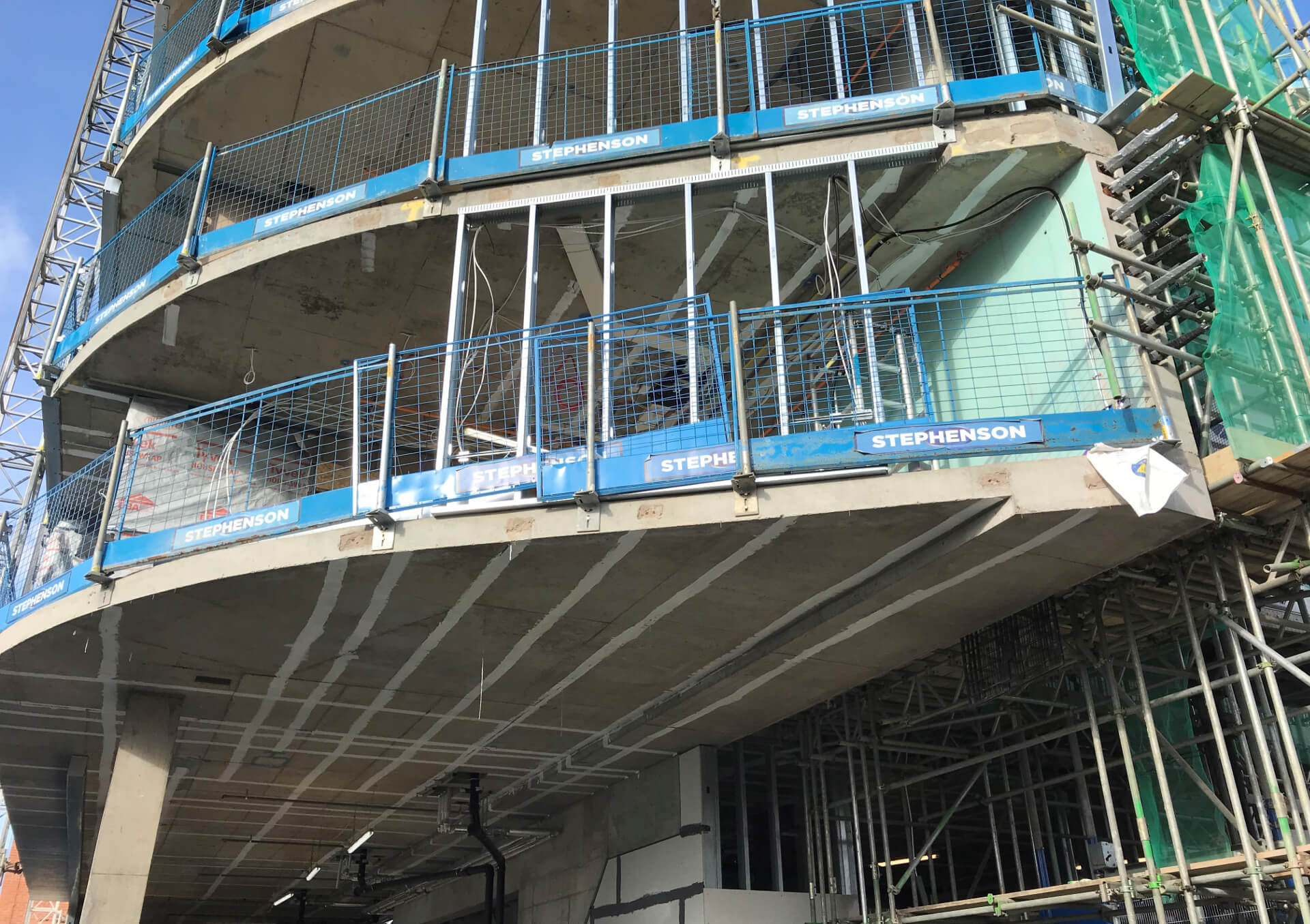
The CCL engineering team completed an in-depth design analysis and closely collaborated with the project’s concrete frame specialist, Stephenson RC Frames, to identify the optimal stressing forces and ideal timing for each of three phased stressing operations. The agreed solution involved stressing one third of the post-tensioning tendons once the concrete element had been cast and reached a compressive strength of 25N/mm2 (typically after three days). This was followed by a second operation to stress another third of the tendons once the building had been constructed up to Level 8. The final operation to stress the remaining tendons took place upon completion of the Level 15 floor slab.
Phasing the stressing process in this way created some logistical challenges for the CCL team because the post-tensioned beam was buried in the ground and the stressing locations at the end of the beam needed to be accessible for all three stressing operations while the building was under construction. To allow this, a pit was excavated by Stephenson RC Frames around the stressing end of the beam. This was large enough to accommodate the stressing jack and the CCL operatives, and was designed to ensure it would remain structurally sound throughout the construction programme.
Maximising Value
The student living development is now completed and fully occupied, offering high quality accommodation while enabling the developer to maximise the value of the site without increasing the construction costs with expensive structural monitoring.